| TX frequency : | 851/869 ~ 894 MHz |
| TX frequency : | 925/936 ~ 965 MHz |
| TX frequency : | 1800 ~ 1990 MHz |
| TX frequency : | 2110 ~ 2170 MHz |
| Total output power : | 160 W |
| 800 MHz: | 40 W |
| 900 MHz: | 40 W |
| 1800-1950 MHz: | 40 W |
| 2100-2200 MHz: | 40 W |
| RF Power output control: | 10W/ 20W/ 30W/ 40W with digital display |
| Signal source: | PLL synthesized |
| RF Cable: | RG214 / 5M (HUBER & SUHNER) |
| Wired Remote control: | RS-485 |
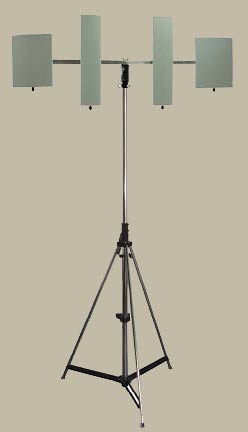
| Sector Antenna: | 10 ÷ 14dBi each band |
| EIRP for each band: | over 400W |
| Cover network standards: | AMPS, N-AMPS, DCS, NMT, TACS, GSM, CDMA, TDMA, IDEN, UMTS |
| Input power: | AC 110-240V / 50-60Hz or DC 20 ~ 28V DC / 35 ~ 40AH |
| Dimension: | 630mm(L)x 492mm(W)x 352mm(D) not include sector antenna. (Pelican 1620 case) |
| Weight: | 35 Kg (approximately) |
| Operating temperature: | -20°C ~ +60°C |
| Humidity: | 5% ~ 90% |
| Jamming range: | 300 ~ 500m based on background signal strength <-80dBm in the given area |